BSP135
SIPMOS® Small-Signal-Transistor
Product Summary
Features
• N-channel
• Depletion mode
VDS
600
V
RDS(on),max
60
W
IDSS,min
0.02
A
• dv /dt rated
• Available with V GS(th) indicator on reel
• Pb-free lead plating; RoHS compliant
PG-SOT223
• Qualified according to AEC Q101
• Halogenfree according to IEC61249221
Type
Type
BSP135
BSP135
BSP135
BSP135
Package
Package
PG-SOT223
PG-SOT223
PG-SOT223
PG-SOT223
Tape and Reel Information
Tape and Reel Information
H6327: 1000 pcs/reel
L6327: 1000 pcs/reel
H6906: 1000 pcs/reel
sorted1000
in VGS(th)
bands 1)
L6906:
pcs/reel
Marking
Marking
BSP135
BSP135
BSP135
BSP135
Packaging
Packaging
Non dry
Non dry
Non dry
Non dry
Maximum ratings, at T j=25 °C, unless otherwise specified
Parameter
Symbol Conditions
Continuous drain current
ID
Value
T A=25 °C
0.12
T A=70 °C
0.10
I D,pulse
T A=25 °C
0.48
Reverse diode dv /dt
dv /dt
I D=0.12 A, V DS=20 V,
di /dt =200 A/µs,
T j,max=150 °C
Gate source voltage
V GS
Pulsed drain current
±20
ESD Class
(JESD22-A114-HBM)
A
kV/µs
V
1A(>250V,2|I D|R DS(on)max,
I D=0.1 A
0.08
0.16
-
S
V DS=3 V, I D=94 µA
-1.2
-
-1
V
K
-1.35
-
-1.15
L
-1.5
-
-1.3
M
-1.65
-
-1.45
N
-1.8
-
-1.6
Transconductance
g fs
W
Threshold voltage V GS(th) sorted in bands3)
J
V GS(th)
2)
Device on 40 mm x 40 mm x 1.5 mm epoxy PCB FR4 with 6 cm 2 (single layer, 70 µm thick) copper area for
drain connection. PCB is vertical in still air.
3)
Each reel contains transistors out of one band whose identifying letter is printed on the reel label. A specific
band cannot be ordered separately.
Rev. 1.33
page 2
2012-11-29
�BSP135
Parameter
Values
Symbol Conditions
Unit
min.
typ.
max.
-
98
146
-
8.5
13
Dynamic characteristics
Input capacitance
C iss
Output capacitance
C oss
Reverse transfer capacitance
Crss
-
3.4
5.1
Turn-on delay time
t d(on)
-
5.4
8.1
Rise time
tr
-
5.6
8.4
Turn-off delay time
t d(off)
-
28
42
Fall time
tf
-
182
273
Gate to source charge
Q gs
-
0.24
0.36
Gate to drain charge
Q gd
-
2.0
3.0
Gate charge total
Qg
-
3.7
4.9
Gate plateau voltage
V plateau
-
0.20
-
V
-
-
0.12
A
-
-
0.48
-
0.78
1.2
V
-
87
130
ns
-
70
104
nC
V GS=-3 V, V DS=25 V,
f =1 MHz
V DD=300 V,
V GS=-3...5 V,
I D=0.1 A, R G=6 W
pF
ns
Gate Charge Characteristics
V DD=400 V, I D=0.1 A,
V GS=-3 to 5 V
nC
Reverse Diode
Diode continous forward current
IS
Diode pulse current
I S,pulse
Diode forward voltage
V SD
Reverse recovery time
t rr
Reverse recovery charge
Q rr
Rev. 1.33
T A=25 °C
V GS=-3 V, I F=0.12 A,
T j=25 °C
V R=300 V, I F=0.1 A,
di F/dt =100 A/µs
page 3
2012-11-29
�BSP135
1 Power dissipation
2 Drain current
P tot=f(T A)
I D=f(T A); V GS≥10 V
2
0.15
1.5
ID [A]
Ptot [W]
0.1
1
0.05
0.5
0
0
0
40
80
120
160
0
40
80
TA [°C]
120
160
TA [°C]
3 Safe operating area
4 Max. transient thermal impedance
I D=f(V DS); T A=25 °C; D =0
Z thJA=f(t p)
parameter: t p
parameter: D =t p/T
100
102
10 µs
limited by on-state
resistance
100 µs
0.5
10-1
0.2
ZthJA [K/W]
ID [A]
1 ms
10 ms
101
0.1
0.05
single pulse
10-2
0.02
DC
0.01
10-3
100
100
101
102
103
VDS [V]
Rev. 1.33
10-4
10-3
10-2
10-1
100
101
102
tp [s]
page 4
2012-11-29
�BSP135
5 Typ. output characteristics
6 Typ. drain-source on resistance
I D=f(V DS); T j=25 °C
R DS(on)=f(I D); T j=25 °C
parameter: V GS
parameter: V GS
0.25
100
10 V
-0.2 V
1V
0.2 V
0V
-0.1 V
0.2
0.5 V
0.1 V
80
0.5 V
RDS(on) [W]
ID [A]
0.15
0.2 V
0.1 V
0.1
60
40
0V
1V
-0.1 V
-0.2 V
0.05
10 V
20
0
0
0
2
4
6
8
10
0
0.04
0.08
VDS [V]
0.12
0.16
0.2
ID [A]
7 Typ. transfer characteristics
8 Typ. forward transconductance
I D=f(V GS); |V DS|>2|I D|R DS(on)max
g fs=f(I D); T j=25 °C
0.25
0.2
0.2
0.15
ID [A]
gfs [S]
0.15
0.1
0.1
0.05
0.05
0
-2
-1
0
1
VGS [V]
Rev. 1.33
0
0.00
0.04
0.08
0.12
ID [A]
page 5
2012-11-29
�BSP135
9 Drain-source on-state resistance
10 Typ. gate threshold voltage
R DS(on)=f(T j); I D=0.01 A; V GS=0 V
V GS(th)=f(T j); V DS=3 V; I D=94 µA
parameter: I D
160
0
140
-0.5
120
98 %
-1
VGS(th) [V]
RDS(on) [W]
100
80
98 %
typ
-1.5
60
-2
2%
40
typ
-2.5
20
0
-3
-60
-20
20
60
100
140
180
-60
-20
20
Tj [°C]
60
100
140
180
Tj [°C]
11 Threshold voltage bands
12 Typ. capacitances
I D=f(V GS); V DS=3 V; T j=25 °C
C =f(V DS); V GS=-3 V; f =1 MHz
101
103
N
M
K
L
J
Ciss
102
C [pF]
ID [mA]
100
10-1
101
Coss
94 µA
Crss
10-2
100
-2
-1.5
-1
-0.5
VGS [V]
Rev. 1.33
0
10
20
30
VDS [V]
page 6
2012-11-29
�BSP135
13 Forward characteristics of reverse diode
15 Typ. gate charge
I F=f(V SD)
V GS=f(Q gate); I D=0.1 A pulsed
parameter: T j
parameter: V DD
100
8
0.5 VDS(max)
0.2 VDS(max)
6
0.8 VDS(max)
25 °C
10-1
150 °C
4
150 °C, 98%
IF [A]
VGS [V]
25 °C, 98%
2
0
10-2
-2
10-3
-4
0
0.5
1
1.5
2
VSD [V]
0
1
2
3
4
5
Qgate [nC]
16 Drain-source breakdown voltage
V BR(DSS)=f(T j); I D=250 µA
700
VBR(DSS) [V]
660
620
580
540
500
-60
-20
20
60
100
140
180
Tj [°C]
Rev. 1.33
page 7
2012-11-29
�BSP135
Package Outline:
Footprint:
Packaging:
Dimensions in mm
Rev. 1.33
page 8
2012-11-29
�BSP135
Published by
Infineon Technologies AG
81726 Munich, Germany
© 2008 Infineon Technologies AG
All Rights Reserved.
Legal Disclaimer
The information given in this document shall in no event be regarded as a guarantee of
conditions or characteristics. With respect to any examples or hints given herein, any typical
values stated herein and/or any information regarding the application of the device,
Infineon Technologies hereby disclaims any and all warranties and liabilities of any kind,
including without limitation, warranties of non-infringement of intellectual property rights
of any third party.
Information
For further information on technology, delivery terms and conditions and prices, please
contact the nearest Infineon Technologies Office (www.infineon.com).
Warnings
Due to technical requirements, components may contain dangerous substances. For information
on the types in question, please contact the nearest Infineon Technologies Office.
Infineon Technologies components may be used in life-support devices or systems only with
the express written approval of Infineon Technologies, if a failure of such components can
reasonably be expected to cause the failure of that life-support device or system or to affect
the safety or effectiveness of that device or system. Life support devices or systems are
intended to be implanted in the human body or to support and/or maintain and sustain
and/or protect human life. If they fail, it is reasonable to assume that the health of the user
or other persons may be endangered.
Rev. 1.33
page 9
2012-11-29
�
很抱歉,暂时无法提供与“BSP135 E6906”相匹配的价格&库存,您可以联系我们找货
免费人工找货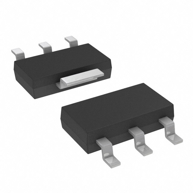


 工商网监
湘ICP备2023018690号
工商网监
湘ICP备2023018690号
